11+ e stop wiring diagram
This is the industry standard. To ensure an emergency stop function the braking torque that is required must be checked.

Mains Wiring An E Stop With Secondary Reset Electrical Engineering Stack Exchange
E Stop Wiring Diagram.

. Find out how to access AutoZones Wiring Diagrams Repair Guide for. The machine is rated for 20A on the mains label. Black or Terminal 2 is 0V or Neutral for 110V an When power is applied to the Red wire or Terminal When power is.
When you make use of your finger or even. Confirm the power is off by touching a non-contact voltage detector to the insulative cover of the wires. Emergency Stop Schematic Circuit Diagram.
Up to 128 cash back Mazda Protégé and Cars 1990-1998 and Ford Probe 1993-1997 Wiring Diagrams Repair Guide. In the case of an across the line motor starter the e-stop switch is wired in series with the coil of the contactor. Now we are onto striping the wires soldering putting on the heatshrink and then.
I would recommend wiring the E-Stop to an input terminal via an NC connection. The customer-supplied E-stop switch must be a positive-opening device. This means that its contact will open when the actuator is pushed with a certain minimum force even if that.
Each leg is pulling 9A under max load though and the contactors on the back of the estop is. Wiring diagram for power supplies l n l n l n switch mode psus and toroidal E stop wiring. The suggestion there is that instead of invoking Abort that you electrically disconnect your motors.
The the active wired brown is attached to the switch. Friday October 14 2022 Latest Projects. Print the cabling diagram off and use highlighters in order to trace the routine.
11 Pics about batteries - Wiring Emergency Stop button to disconnect two independent. The E-STOP you describe. Power to motor live 24.
On the Switch the Red Tab is the Normally Closed contacts. 3 reds 2 yellow 2 green Learn More. E-stop E-stop switches are wired into the control circuit only.
Required Materials to build vfd start stop wiring diagram. I have an 8 relay. M-F 11am-3pm PST Office.
Print the cabling diagram off and use highlighters in order to trace the routine. The switches are mechanically latche and IEC 60947-5-5. Cut the power wire for the device on which are installing the E.
RFID Based Attendance System Circuit Working Source Code. Typical Wiring Diagrams For Push Button Control Stations Start-Stop Control Wiring Diagrams 4 SINGLE STATION - MAINTAINED CONTACT PUSH BUTTONS t-----t L1 UNDERVOLTAGE. It requires a NC Normally connected circuit for the machine to.
The single wire safety output l11 and the auxiliary output y32 are off. 27758 Santa Margarita Parkway 336 Mission Viejo CA 92691. Get The Best Result With ZapMeta About E Stop Button Wiring.
If the holding brake fulfills the dynamic requirements it must be taken into acount. 250 Voltage Universal Ck21d 250v Safety Switch Emergency Stop S Afe Cut Off Waterproof And Dustproof Switches Electromagnetic For Grinding Machine. 2 Stop1start1 Push Button NO.
Batteries - Wiring Emergency Stop button to disconnect two independent. Wiring schematic for G0704. This part presents basic examples in which a G9SA Safety Relay Unit G9SX Flexible Safety Unit F3SX Safety Controller and F3SP-B1P Safety Light Curtain Controller.
The wires are joined. I found a reference to e-stop in the G code support for TinyG. Here the wiring is completed.
Search E Stop Button Wiring. CONTACT US E-Stopp Corporation Mailing Address. When you make use of your finger or even.

Emergency Stop Button 10 Steps With Pictures Instructables
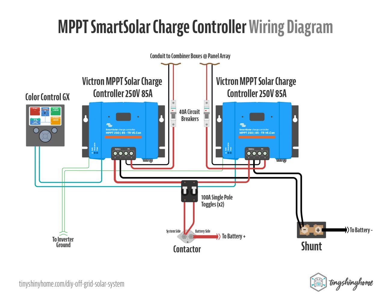
Diy Off Grid Solar Power System For Homestead Installation Wiring Guide Tiny Shiny Home

Kaabo Electric Scooters Uk Eu Wiring Diagrams For Mantis Scooter Facebook

I Have A Whirlpool Gold Series Microwave I Need To Get Pictures Of The Inverter Wiring For A Wiring Diagram That Will

Hitachi Zx135us 5b Hydraulic Excavator Electrical Hydraulic Circuit Diagram 1 By Heydownloads Issuu

Vsett 10 Unofficial Scooter Manual Feedback Please Other Scooter Owners May Find Useful R Electricscooters

Manual Instalare Programare Bft Virgo Pdf Power Supply Mains Electricity

E Stop Wiring Model Engineer
![]()
Figure 8 Diagram Hi Res Stock Photography And Images Alamy

Connecting E Stop To System Inventables Community Forum

How To Connection Timed Motor With Emergency Stop Wiring Diagram Youtube
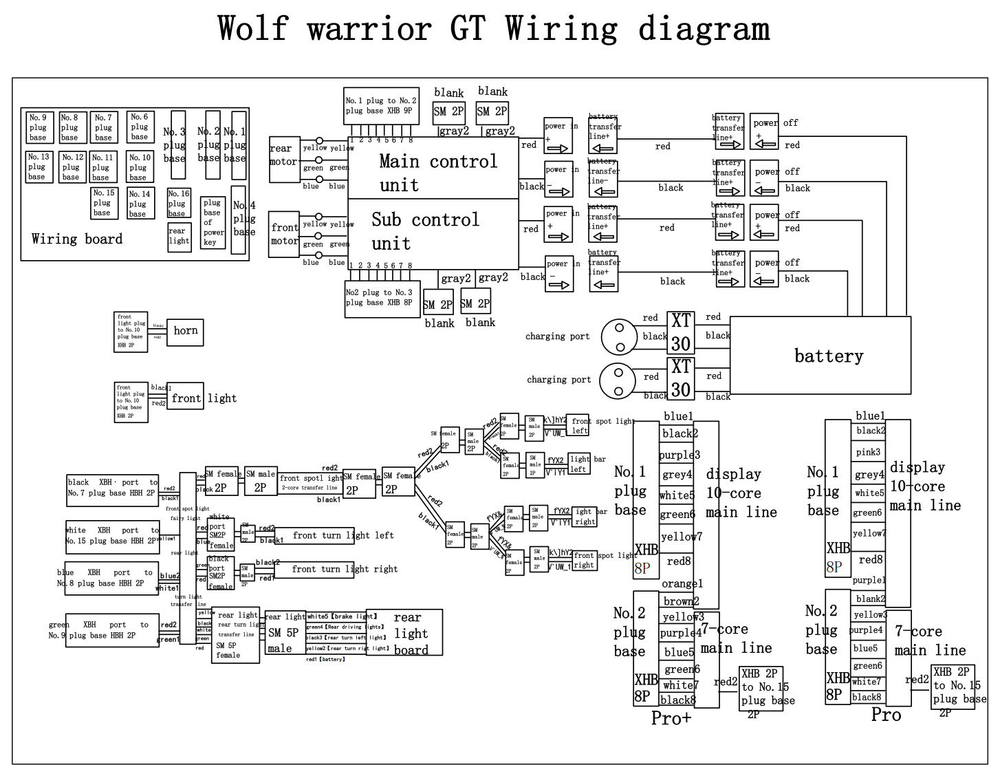
Kaabo Spares

Circuit Diagrams Of Safety Components Technical Guide New Zealand Omron Ia

Hitachi Zh 210 6 210lc 6 Hybrid Excavator Electrical Hydraulic Circuit Diagram By Heydownloads Issuu

Circuit Diagrams Of Safety Components Technical Guide Australia Omron Ia
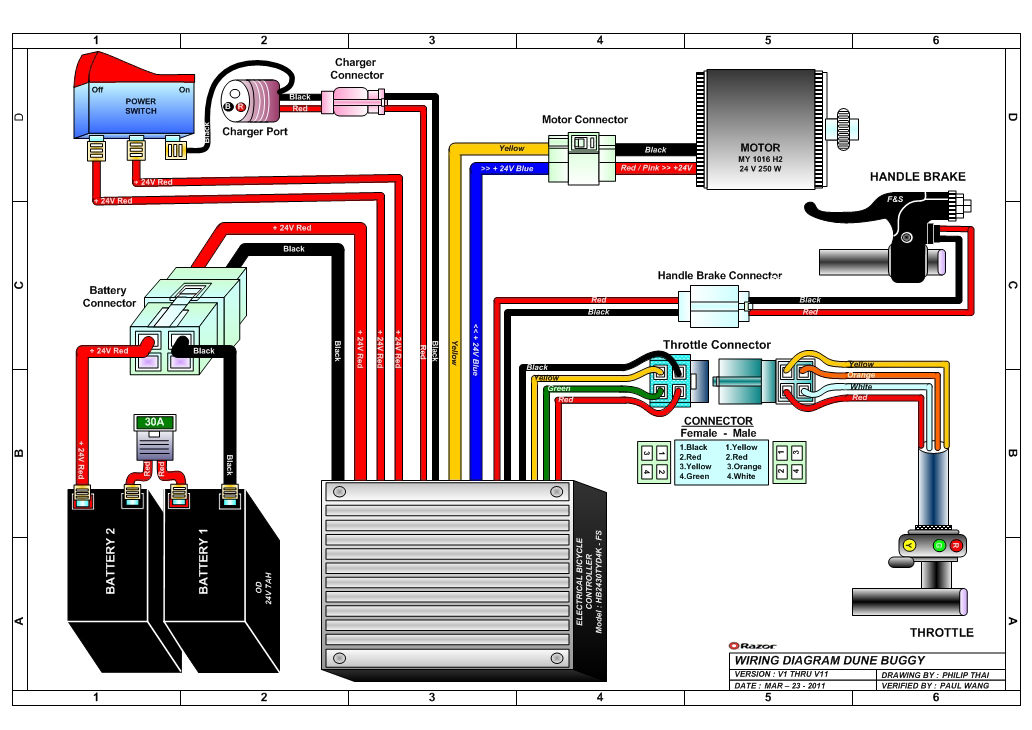
Razor Manuals

Circuit Diagrams Of Safety Components Technical Guide Australia Omron Ia